Quick Answer: Decision Checklist
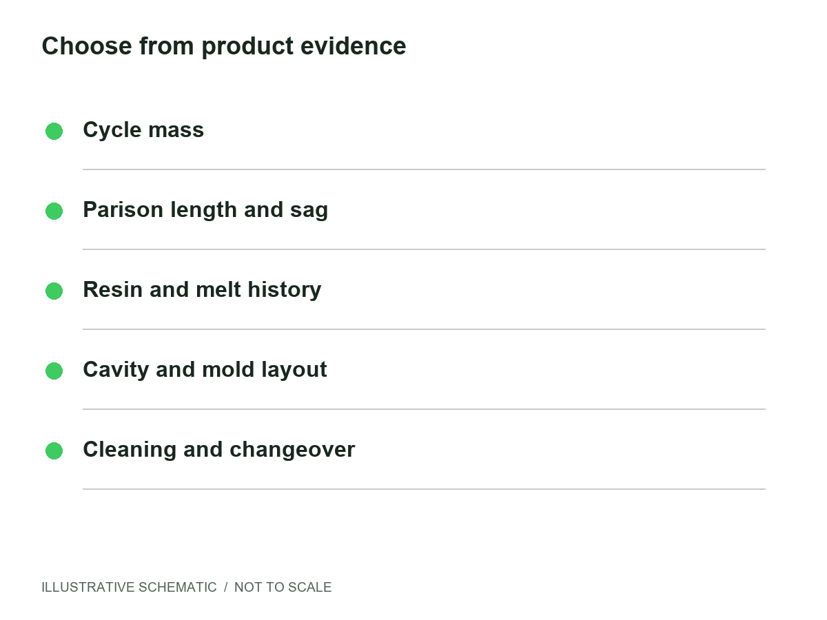
Choose by cycle mass and parison behavior, then verify the complete production sequence. There is no universal litre cutoff.
- Count finished parts, flash, tails and trim across every cavity; show any capacity reserve separately.
- Check the time a long or heavy parison hangs before mold closing and whether melt strength is adequate.
- Use the actual resin grade, colorant and regrind policy for melt-history and purge assessments.
- Confirm head spacing, cavity count, mold envelope and required parison diameter.
- Compare sustained good parts per hour with identical quality and downstream scope.
- Ask for cleaning access, changeover waste and a documented factory acceptance test (FAT).
How Continuous Extrusion Works
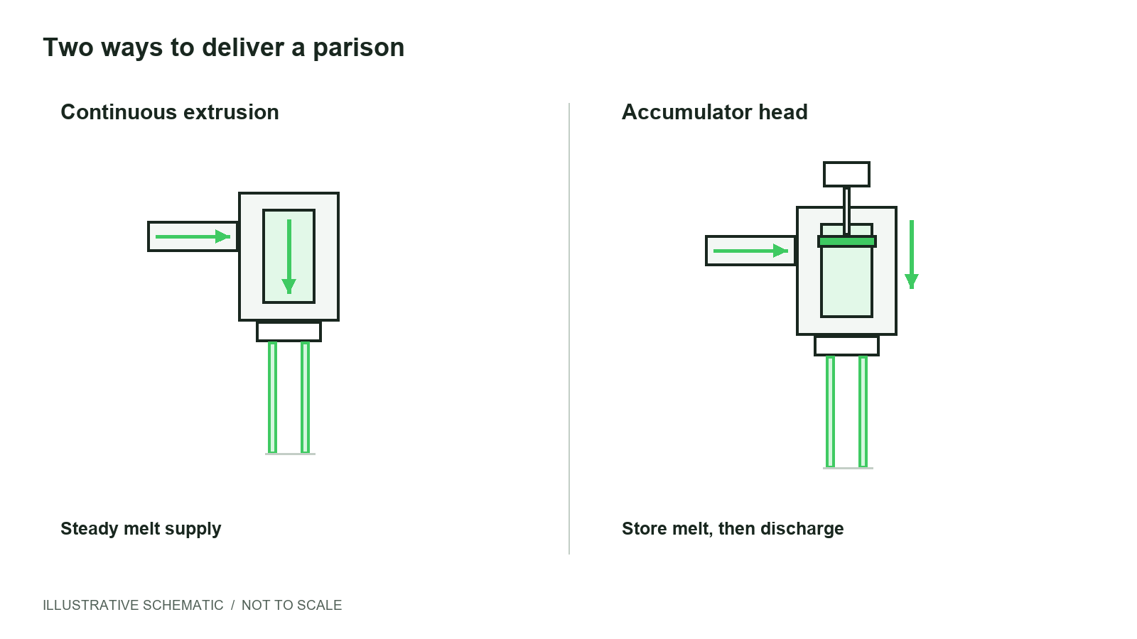
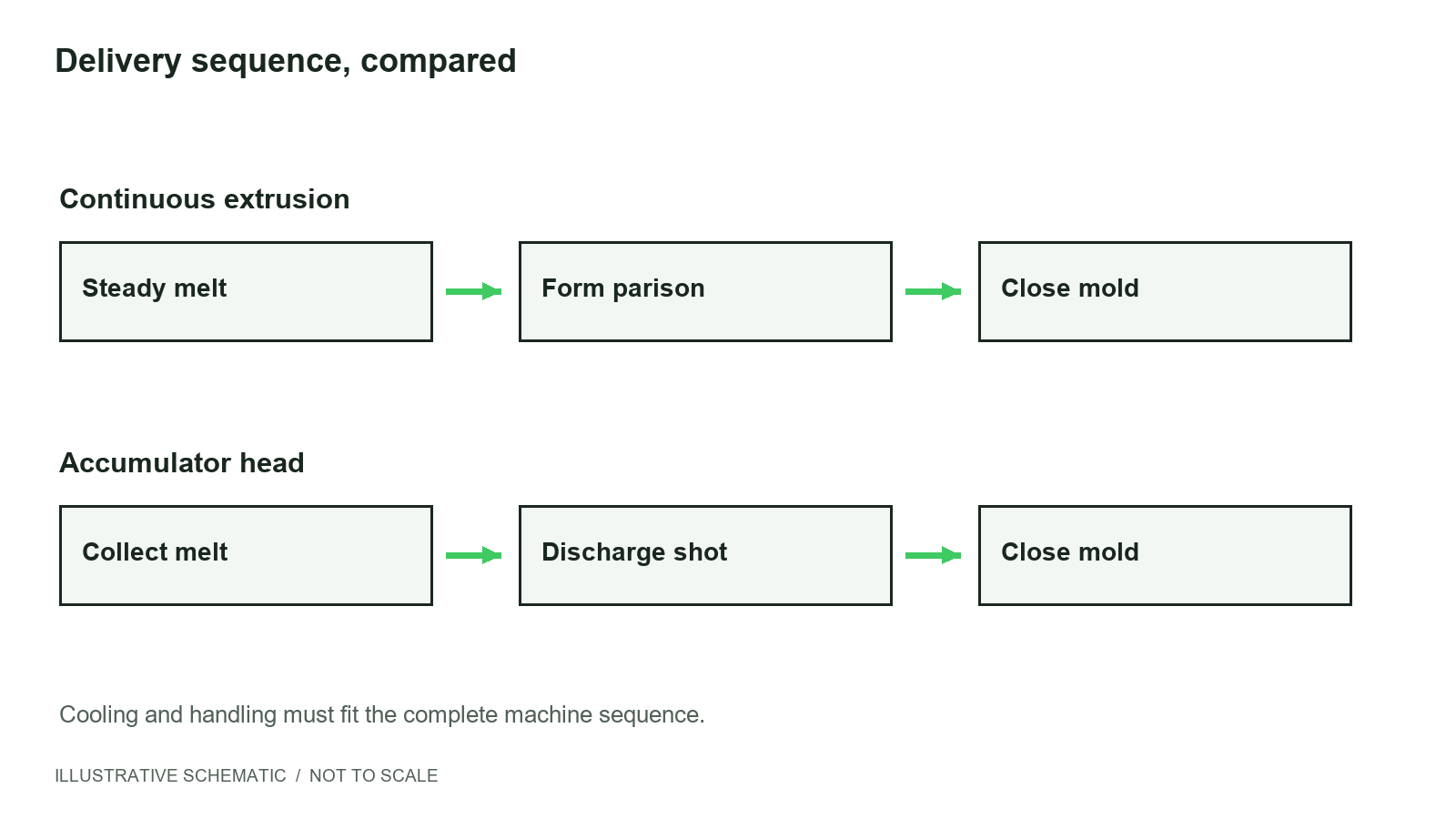
The screw plasticizes the resin and supplies melt continuously to an annular die, which forms a hollow tube called a parison. Once the required length is available, the mold closes around it, the parison is separated and air inflates it against the cavity. The part cools before removal and trimming.
The next parison can form while another part is being cooled or handled, depending on the station and mold movement. A usable process must coordinate these overlapping operations: ongoing extrusion is helpful only when the mold and downstream equipment can accept the material consistently.
For a light product family, a multi-head or alternating-station concept may be worth assessing. Head spacing, melt distribution, parison formation time and cooling must support that layout; head count alone is not proof of output.
How an Accumulator Head Works
Melt collects inside a chamber in the head. When the required charge and mold sequence are ready, a ram or plunger pushes the stored melt through the die, forming the parison quickly. Shorter discharge can reduce the time a heavy or long parison stretches under its own weight.
“Discontinuous” describes the separate discharges at the die. It does not necessarily mean the screw stops plasticizing between shots. Review the actual filling and discharge sequence, usable shot capacity, wall-thickness programming and melt residence conditions with the supplier.
Fast discharge cannot compensate for an unsuitable resin, poor temperature control or inadequate mold closing. Prove the resulting wall distribution and repeatability on accepted parts.
Side-by-Side Comparison
| Consideration | Continuous extrusion | Accumulator head |
|---|---|---|
| Melt delivery | A steady supply forms the parison in the repeating sequence. | A chamber collects melt for a separate discharge. |
| Product tendencies | Lighter parisons and compatible repeated or multi-head production. | Heavier or longer parisons where hanging time is a concern. |
| Selection evidence | Formation time, stable extrusion and melt strength. | Usable shot mass, discharge profile and recharge time. |
| Output strategy | Coordinate parison supply with cavities, stations and cooling. | Balance discharge, recharge, cooling and removal. |
| Cleaning / color change | Review die and flow-path access, purge endpoint and waste. | Also review the chamber, ram and stored-melt path. |
| Structural complexity | Evaluate the complete head, station and handling concept. | Adds storage and discharge mechanisms; service access matters. |
These are qualitative tendencies. Either proposal needs a product-specific mold, material and acceptance review. Neither column is a Waley model specification.
Why Litres Alone Mislead: The 20 L Overlap Zone
Imagine two containers with the same 20 L internal volume. One is relatively light and compact. The other has a wider body, heavier base, deep handle or demanding wall target. They hold the same quantity, but their material budgets, parison dimensions and cooling requirements differ.
Continuous extrusion may be feasible for the lighter design if parison formation and mold closing fit the material’s process window. The heavier or wider design may favor a stored shot to deliver the parison promptly. An open-top drum also changes the flash and trimming layout. None of these features establishes a universal switch point.
When two quotations disagree, compare their product assumptions first. A proposal based only on nominal litres may be solving a different weight, mold or output requirement.
Manufacturer perspective: I-TOP’s architecture comparison discusses the 20 L overlap. Its machine examples and production figures are not Waley data or general capacity limits.
Decision Matrix: Five Factors to Evidence
| Factor | What the supplier should show |
|---|---|
| Total cycle mass | A mass budget for every cavity, including flash and trim, plus a separately stated reserve. |
| Parison length & sag / melt strength | A proposed parison profile and trial evidence that mold closing occurs before unacceptable stretching or cooling. |
| Resin behavior & melt residence | The specified grade, temperature window, expected melt history and restart / shutdown procedure. |
| Cavity / head layout & mold envelope | A layout drawing covering head centers, mold dimensions, travel, opening and handling clearance. |
| Cleaning, changeover & purge waste | A demonstrated access and purge method with a defined color / contamination endpoint and collected waste. |
Record assumptions beside each item, rather than assigning an architecture a generic score. For example, changing the resin or increasing cavity count can invalidate a previously acceptable sequence. Repeat the review when the product revision changes.
Output Myths: Continuous ≠ Always Faster; Accumulator ≠ Always Higher Throughput
Neither architecture guarantees higher output by name. Compare sustained good parts per hour under the same product, resin, mold, cooling and acceptance definition. A short empty-machine movement is not a production cycle.
Continuous delivery can be limited by parison supply, cooling, mold movement or downstream equipment. An accumulator can discharge quickly yet spend longer recharging or waiting for the part to cool. Extra cavities help only if extrusion, mold width, finishing and handling support them.
Ask for a cycle breakdown and a trial report covering the agreed duration. Record rejects, trimming losses, restarts and any excluded auxiliaries. Define whether the target concerns molded parts or finished, leak-tested containers ready for the next operation.
What to Send So Both Architectures Are Compared Fairly
- The same revision of the product drawing or a sample, with overall size, neck finish, handle and opening details.
- Target net weight and tolerance, minimum wall distribution or performance requirements, and inspection methods.
- Resin grade, additives, color plan and regrind policy; identify heat-sensitive materials.
- Required good parts per hour, shift pattern, product mix and changeover frequency.
- Any preferred station, head or cavity concept, existing mold data and finishing equipment.
- Available electricity, compressed air and cooling, including the measurement and equipment boundaries.
- FAT conditions, sampling and acceptance criteria, plus a request for written assumptions and exclusions.
Send one RFQ package to every supplier. Ask each to return the same mass budget, layout, cycle basis and quality evidence so you can compare the proposals fairly.
Where This Page Fits Next
If the product points toward an accumulator head, continue with the drum-sizing method to check shot mass, clamp requirements, recharge time and mold fit.
If a continuous small-bottle concept is the leading candidate, first document cavities, stable melt supply, cooling and accepted output. Use the servo vs hydraulic guide to evaluate the separate question of machine drives; a drive label does not settle head architecture.
Waley Machinery’s Lines
WLA, WLU and WLC (Customized) are series names to discuss with Waley Machinery. The series-to-architecture mapping and application-specific configuration are TBC; request confirmation in the proposal.
Begin with your product drawing, material, mass budget and production needs. Ask for written head architecture, mold limits, usable capacities and trial conditions. This guide does not assign unconfirmed capabilities or performance figures to any Waley series.
FAQ
Practical answers for your machine shortlist.
What is the difference between continuous extrusion and accumulator head blow molding?
Continuous extrusion makes a tubular parison from an ongoing melt supply coordinated with the molding sequence. An accumulator head collects melt and pushes out a separate shot when required. The choice depends on cycle mass, parison behavior, material, mold layout and cleaning requirements rather than a container-volume label.
Is there a container volume where I must switch to an accumulator head?
There is no universal litre cutoff. Equal-volume containers can have different weights, widths, handles and wall requirements, creating different parison demands. Ask suppliers to assess the same drawing, resin and total cycle mass, then explain why their proposed head and mold sequence can meet your acceptance criteria.
Can a 20 L jerry can run on either system?
Either architecture may be a candidate for a 20 L jerry can, depending on its design. A lighter, compact container and a heavier, wider industrial container can need different parison delivery. Confirm weight, geometry, melt strength, mold space and required accepted output before choosing either proposal for production.
Does continuous extrusion always give higher output?
No. A continuous melt supply does not guarantee more accepted parts per hour. Extruder capacity, head count, mold layout, cooling, trimming, leak testing and handling can limit production. Compare sustained good-part output using the same product, resin, quality definition and trial duration, including the downstream equipment in the agreed scope.
Does an accumulator head always produce more per hour on large parts?
No. Rapid discharge helps deliver a heavy parison before excessive hanging, but recharge, mold closing, cooling and removal still take time. A large shot rating is not an hourly-output guarantee. Require a complete cycle breakdown and a sustained trial with the intended resin, mold, auxiliaries and accepted-part criteria.
What is cycle mass and why does it matter more than litres?
Cycle mass is the plastic required for all cavities in a cycle, including finished parts, flash, tails and other trim. Record any capacity allowance separately. Container litres describe internal volume, while cycle mass determines melt delivery and recharge demand. Both mass and product geometry are needed for a useful architecture comparison.
How do cleaning and color change differ between the two heads?
Both heads need a documented purge procedure, access plan and acceptance standard for the next material or color. An accumulator adds a storage chamber and its flow path to the review. Actual purge time and waste depend on head design, resin, color contrast and operating practice; request a representative changeover demonstration.
What information should I send to compare both options fairly?
Send the product drawing or sample, net weight and tolerance, resin grade, dimensions, neck and handle details, wall or performance targets, mold concept and required good parts per hour. Include shifts, utilities, finishing equipment and factory acceptance criteria. Give each supplier the same revision and require written assumptions and exclusions.
Which Waley series is continuous and which is accumulator?
WLA, WLU and WLC are Waley series names. The series-to-architecture mapping for your proposed configuration is TBC and should be confirmed during application review. Send the product drawing, material and cycle-mass basis, and request written confirmation of the head architecture, machine functions and scope before comparing or ordering equipment.
How does this choice relate to clamping force and shot size?
Architecture defines how melt reaches the mold; shot size and clamping force check different capacity requirements. Calculate the full material budget, prove usable shot capacity with the production resin, and assess pressure acting on projected area plus pinch-off needs. The linked drum-sizing guide explains the sequence without assigning a universal machine tonnage.
Send your drawing, target weight and output basis for an architecture review
Share the product revision, resin, mold information and accepted-output requirements. Ask for the proposed configuration, calculations and trial conditions in writing.
Discuss your application / RFQwaleymachinery@gmail.com