
Quick Answer: The 5-Step Sizing Method
Size from total material per shot, not the litres printed on the drum drawing. This guide covers a 20L–200L product topic; it does not state a Waley model’s capacity range.
- Build a shot budget from the finished drum, flash and trim, with the process reserve identified.
- Confirm usable accumulator volume and deliverable shot mass with the specified production resin.
- Check clamping force from projected area and blowing pressure, then assess pinch-off and structural requirements.
- Balance stable extruder output and available accumulation time against the molding cycle.
- Verify the die, parison control, mold envelope, opening stroke and handling arrangement.
First confirm the head architecture in continuous extrusion vs accumulator head. The five checks above are expanded into six practical steps below, starting with the product definition.
Why Large Drums Need an Accumulator Head
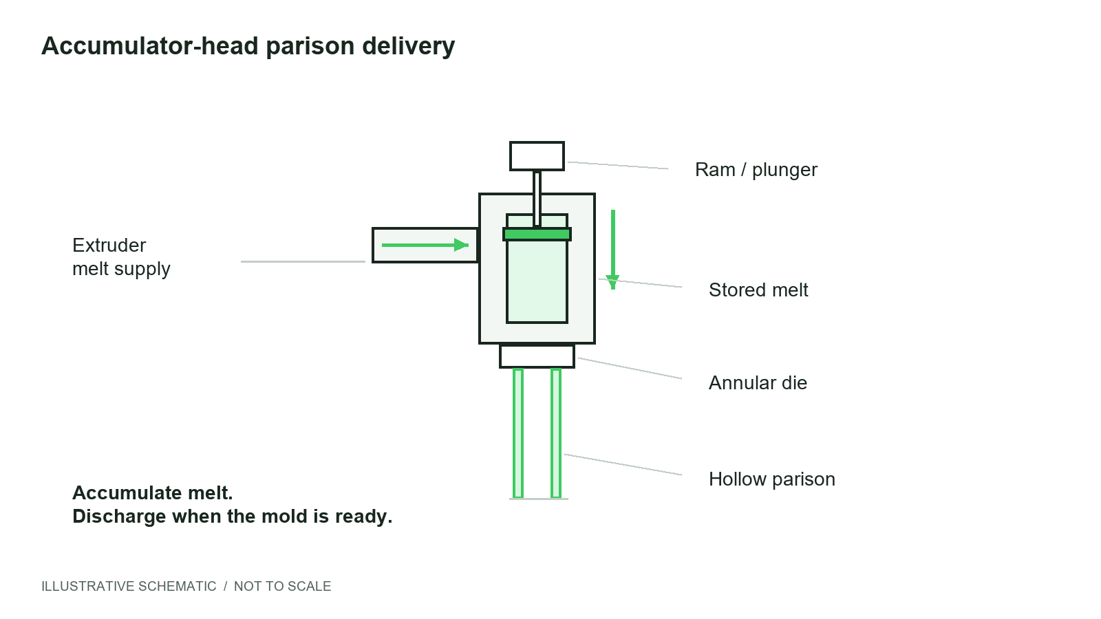
A long or heavy parison can sag and lose heat while it hangs before the mold closes. Storing melt and discharging it quickly can reduce that exposure, which is why accumulator heads are often considered for large drums.
“Large” is a starting clue, not a selection rule. Evaluate actual parison mass, geometry, resin melt strength and mold closing time. Rapid discharge must still produce the required wall distribution, and the extruder must recharge the head within the agreed sequence. Container volume alone cannot establish that continuous extrusion is unsuitable.
Step 1 — Start From the Drum, Not the Litres
Collect a drawing or 3D model, target finished weight and tolerance, minimum wall requirements, neck and closure dimensions, and whether the drum has an open top, integrated handle or L-ring. Specify the resin grade, including any HMW-HDPE requirement, colorant and permitted regrind content.
Two 200L designs can need different material quantities and mold concepts. A heavier base, wider body or different ring geometry changes the parison and cooling demands even when nominal capacity stays the same. Use the approved product specification rather than a generic drum weight.
Identify the critical SKU for each constraint. The product with the highest shot mass may differ from the widest mold or the part with the longest cooling time.
Step 2 — Calculate Total Shot Weight
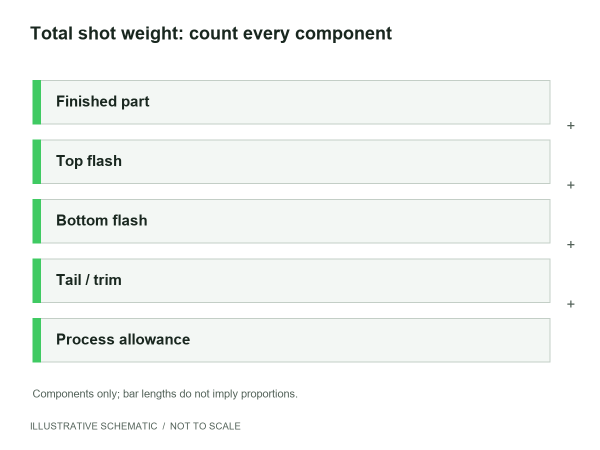
Required shot mass = finished part + top flash + bottom flash + tail / trim + process allowance
Sum the material for all cavities. Define the flash and trim regions so that the same piece is not counted twice. Obtain their estimates from the proposed mold and parison plan; there is no universal flash percentage. Show the operating reserve separately and keep startup purge outside recurring consumption records.
| Input / result | Record and verify |
|---|---|
| Finished drum | Target net mass, tolerance, drawing revision and cavity count. |
| Top / bottom flash | Separate estimates from the proposed mold and pinch-off layout. |
| Tail and other trim | Mass not already included in the flash entries. |
| Process / startup allowance | Separate usable-capacity reserve from one-time startup or purge waste. |
| Total required shot | Sum of the documented mass components and defined reserve. |
| Regrind | Material source, permitted proportion and trial conditions; recycled trim still passes through the head. |
| Measured accumulator capability | Maximum deliverable and normal operating shot with the specified resin. |
Have the supplier update estimates with weighed trial material. Returning flash as regrind does not remove it from the shot that must pass through the accumulator.
Step 3 — Convert Shot Weight to Accumulator Volume
Accumulator capacity is a volume; shot weight is a mass. The kilograms available from a chamber depend on melt density at the process conditions and on the usable discharge stroke. Solid-pellet bulk density is not the correct conversion basis.
Required usable melt volume (L) = required shot mass (kg) ÷ melt density (kg/L)
Use resin-specific melt data agreed with the supplier, then verify deliverable mass in a trial. Gross chamber volume, maximum deliverable shot and normal working shot are different quantities. Confirm the remaining control reserve at the normal setting; do not treat a catalogue maximum as proof of stable continuous production.
No universal litres-to-kilograms factor is used here. A supplier’s published volume / shot pair applies only to its stated material, machine and test conditions.
Step 4 — Estimate Clamping Force
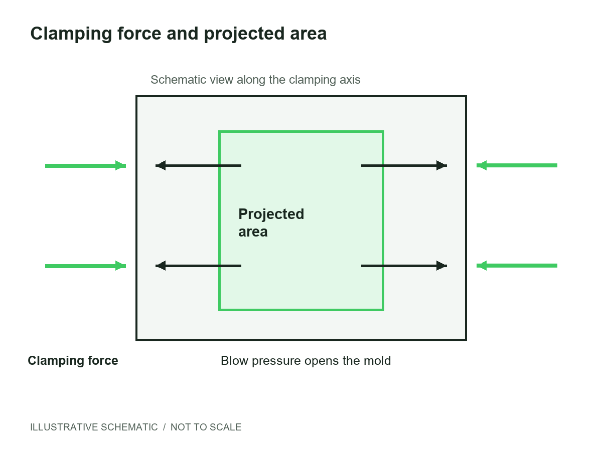
Blowing pressure creates an opening load over the part and flash area projected perpendicular to the clamping axis. Use the applicable mold projection rather than container volume or the developed surface area of the drum. The clamp must resist opening and provide the required pinch-off behavior.
F (kN) = A (cm² per cavity) × P (bar) × 0.01 × N × K
Here A is the projected area including relevant flash, P is the design blowing pressure, N is cavity count and K is a documented design factor. The coefficient follows from the units: 1 bar = 100,000 N/m² and 1 cm² = 0.0001 m², so 1 bar × 1 cm² = 10 N = 0.01 kN.
If A already includes all cavities, do not multiply by N again. This pressure-load estimate does not by itself resolve pinch-off force, frame and platen stiffness, tie-bar loading or load distribution. Require the machine supplier’s complete calculation and mold assessment.
Why do suppliers quote different forces for “200L”? They may assume different geometry, flash, pressure, reserve or force definitions. Unit errors also create large discrepancies. Compare the same drawing and pressure basis in kN; distinguish tonne-force from machine mass. A higher headline clamp rating does not establish better wall quality or a suitable frame.
Step 5 — Balance Extruder Output With the Cycle
Accumulation time (min) = recurring shot mass (kg) ÷ stable melt output (kg/min)
Use stable output measured with the production resin, color and regrind policy. Convert kg/h to kg/min by dividing by 60. An extruder’s theoretical maximum is not the rate available under every melt-temperature or material condition.
Compare recharge time with the actual accumulation window in the supplier’s sequence, including mold closing, blowing, cooling, opening and removal where those operations overlap with filling. If recharge takes longer than that window, extrusion limits the cycle. If filling finishes much earlier, review stored-melt residence and the control strategy.
Validate the whole line: trimming, leak testing, conveyors and cooling can limit accepted output even when shot capacity and extrusion appear sufficient.
Step 6 — Check Die Size, Parison Control and Mold Envelope
- Match the die diameter and gap range to the required parison, allowing for resin behavior and die swell.
- Confirm parison programming capability and demonstrate the required wall profile on sectioned trial parts.
- Check mold width, height, thickness, mounting interfaces, mass and support against the proposed machine.
- Verify opening stroke, daylight, blow-pin travel and removal clearance, including handles and L-rings.
- Plan lifting, maintenance access, cooling connections, trimming and safe part handling.
Request a layout drawing and interface list. A large enough shot does not prove that the mold fits, the drum can be removed or the wall profile can be controlled.
Worked Example (Illustrative Only)
Every numerical input below is assumed for illustration for a hypothetical 200L drum. None is a Waley specification, a production measurement or a machine recommendation. The example shows the calculation sequence; actual values require product, material, mold and supplier review.
| Check | Illustrative calculation |
|---|---|
| Mass budget | Assume one cavity: 8.0 kg finished drum + 0.6 kg top flash + 0.7 kg bottom flash + 0.3 kg other trim + 0.4 kg capacity allowance = 10.0 kg shot-capacity budget. |
| Usable melt volume | Assume melt density of 0.75 kg/L solely for this example: 10.0 ÷ 0.75 = 13.33 L usable melt volume. Gross chamber size and deliverable stroke still need verification. |
| Pressure-load estimate | Assume A = 6,000 cm² per cavity, P = 6 bar, N = 1 and K = 1.2: 6,000 × 6 × 0.01 × 1 × 1.2 = 432 kN. This is not a final required machine rating. |
| Recharge check | Using the conservative 10.0 kg budget and an assumed stable rate of 2.0 kg/min: 10.0 ÷ 2.0 = 5.0 min. If the available recharge window is assumed to be 4.0 min, this combination fails the timing check. |
| Mold / tooling check | No mold dimensions, usable discharge-stroke data or pinch-off assessment have been assumed. A final machine size cannot be selected from these calculations. |
The 0.4 kg reserve is a capacity allowance, not automatically a recurring extra mass. Replace the conservative recharge budget with the agreed actual shot during a trial. Do not infer accepted drums per hour until cooling, handling, yield and the complete sequence are established.
What Changes From 20L to 200L
As the product family changes, shot mass, parison length, projected area, mold size and cooling demand change too. They do not all scale in direct proportion to nominal litres. Weight, geometry, material and performance requirements must be reviewed for every SKU.
One machine may cover several molds only if each fits the mold envelope, opening stroke and usable shot-control range. Assess tooling changes, small-shot stability, residence time and handling as well as the largest product. The 20L–200L topic range on this page is not a statement that a WLA model covers every size.
UN-Rated Drums: What the Machine Can and Cannot Do
UN packaging approval applies to the drum design and its applicable tests, not to the blow molding machine. Closed-head and open-head plastic drums can fall under different packaging design codes, such as 1H1 and 1H2. The applicable contents, packaging group and transport requirements must be established for the intended use.
Drop, stacking, leakproofness and hydraulic-pressure tests apply as required for the packaging and intended service. The molding process contributes weight consistency, wall distribution and repeatability; it cannot confer a drum approval simply by using a particular machine.
Agree the design qualification and production checks with the responsible packaging specialist and test organization. No Waley machine certification or drum performance approval is claimed here.
Regulatory reference: 49 CFR Part 178, Subpart M addresses testing of non-bulk packagings. Confirm the rules applicable to your shipment and packaging design.
RFQ Checklist: Data to Send Your Supplier
- Product drawing / 3D model and revision; target weight, tolerance, minimum wall and performance requirements.
- Resin grade, colorant, regrind policy and relevant material-processing limits.
- Shot table covering finished material, every flash / trim region and separately identified reserve.
- Die concept, parison program, mold dimensions and weight, mounting details and removal clearance.
- Clamp calculation showing projected area, pressure, cavity basis, units, design factor and pinch-off review.
- Required accepted output, shifts, cycle assumptions, cooling, finishing, leak testing and handling.
- Available power, air and water; equipment boundaries and any site integration constraints.
- FAT product, resin, sampling plan and acceptance limits; requested evidence, scope and exclusions.
Request a written response to every missing input. Compare usable production capability and accepted output, not only maximum accumulator volume or a nominal drum-size label.
WLA Accumulator Series
Discuss the WLA accumulator series with Waley Machinery using your drum drawing, resin and shot budget. Model-specific shot capacity, accumulator volume, clamping force, extrusion rate, mold limits and supported product range are TBC for the proposed application.
Request confirmation in the quotation and a trial plan tied to the product acceptance criteria. For the separate drive-system question, read servo vs hydraulic blow molding machines. For head-architecture selection, return to continuous extrusion vs accumulator head.
Where This Page Fits Next
Confirm head architecture before you lock sizing numbers. If continuous extrusion versus an accumulator head is still open, use the continuous vs accumulator guide.
Drive choice is a separate question from shot weight and clamp. Compare options with the servo vs hydraulic guide after the product and mold envelope are clear.
FAQ
Practical answers for your machine shortlist.
What size blow molding machine do I need for a 200L drum?
A 200L label does not identify one machine size. Start with finished weight and all flash and trim, then check usable shot capacity with the chosen resin. Calculate clamp requirements, balance recharge with the molding cycle, and confirm mold space, opening stroke and handling. Request an application-specific proposal and trial.
How do I calculate shot weight for an accumulator head machine?
Add the finished-part weight, top flash, bottom flash, tail and other trim for every cavity, then document the process allowance. Avoid counting the same trim twice. Record startup purge separately from recurring consumption, and ask the supplier to verify the mass budget against the proposed mold and parison during trials.
Is accumulator volume (litres) the same as shot weight (kg)?
No. Litres measure volume and kilograms measure mass. Conversion depends on the resin’s melt density under the stated process conditions and on how much chamber volume is usable. Ask for maximum and normal deliverable shot weights with your production resin, including the control reserve, rather than relying on a universal conversion factor.
How is clamping force calculated for blow molding?
A preliminary pressure-load estimate multiplies projected area per cavity in square centimetres by blowing pressure in bar, by 0.01, by cavity count and by a documented safety factor, giving kilonewtons. If area already includes all cavities, omit the extra cavity multiplier. The supplier must also assess pinch-off and machine stiffness.
Why do suppliers quote very different clamping forces for 200L drum machines?
The same nominal volume can represent different projected areas, flash layouts, pressures and pinch-off demands. Suppliers may also quote different force definitions or units and use different margins. Request the calculation, force rating basis, mold drawing and frame assessment. Compare kilonewtons consistently instead of treating conflicting catalogue tonnage bands as equivalent.
Can one machine produce 20L, 60L and 200L drums?
It may be possible, but the capacity range alone cannot prove suitability. Each mold must fit the platens and opening stroke; each shot must fall within the usable control range. Check die tooling, parison control, cooling, extrusion stability, changeover and handling for every product. No Waley coverage across these sizes is asserted here.
Why do large drums need an accumulator head instead of continuous extrusion?
A heavy or long parison may stretch or cool excessively while hanging before the mold closes. An accumulator can discharge stored melt quickly and reduce that exposure. This makes it a useful candidate for many large drums, but volume alone does not require it; verify the actual mass, geometry, resin and sequence.
Does the blow molding machine need to be UN certified?
UN packaging approval concerns the drum design and its applicable performance tests, not a certification supplied by the molding machine. The machine helps control weight, wall distribution and repeatability. Agree the intended contents, packaging design and testing route with the responsible packaging specialist; a machine specification cannot replace successful drum testing.
How do I check the extruder output is enough?
Divide the recurring shot mass in kilograms by stable melt output in kilograms per minute to estimate recharge time. Compare it with the actual time available for accumulation in the agreed sequence. Use production-resin trial data and account for interruptions and process reserve; theoretical maximum extrusion output is not sufficient evidence.
What information should I send for a machine quotation?
Send the drum drawing or model, material grade, regrind policy, target weight and tolerance, minimum wall requirements, neck, handle and ring details, and preliminary shot budget. Include mold dimensions, output basis, finishing and leak tests, utilities and factory acceptance criteria. Request calculations, usable capacities, trial evidence and clearly listed scope exclusions.
Send your drum drawing and target weight for a sizing review
Share the product revision, resin, mold information and accepted-output requirements. Ask for the proposed configuration, calculations and trial conditions in writing.
Discuss your application / RFQwaleymachinery@gmail.com